
Variable Frequency Drives (VFDs) have transformed how plants control motor speed and energy consumption, but they also introduce a serious side effect: shaft currents that damage bearings. Electrically insulated bearings are one of the most effective ways to block these destructive currents and keep VFD motors running reliably. This guide explains, in practical engineering terms, why VFD motors need insulated bearings, how they work, where to use them, and how to specify them correctly.
How VFDs Create Shaft Currents
PWM Switching and Common-Mode Voltage
A VFD controls motor speed using high-frequency pulse-width modulation (PWM). Instead of a smooth sine wave, the motor terminals see rapid voltage pulses with steep edges (high dv/dt). These pulses create common-mode voltages between the stator windings and the rotor/shaft. That voltage wants to return to the drive, and if no safe path is provided, it will discharge through the bearings.
Bearing Current Mechanisms in VFD Motors
VFD motors see several types of bearing currents:
- Capacitive discharge currents: The stator, rotor, and frame form a capacitive network. At each PWM transition, charge stored in these “capacitors” can discharge through the bearings if the lubricant film breaks down.
- Circulating currents: In larger machines, magnetic asymmetry can create current loops that flow from one end of the shaft to the other through both bearings.
- High-frequency EDM currents: When the electrical field across the lubricant exceeds its breakdown strength, tiny arcs jump across the film, melting microscopic pits in the raceway.
Over time, these effects cause electrical erosion-pitting, fluting, and lubricant degradation that leads to early bearing failure, often well before the mechanical L10 life is reached.
What Happens When Bearings Are Not Protected
Electrical Pitting and Fluting
Unprotected bearings in VFD motors typically exhibit:
- Frosted raceways with fine craters (electrical pitting).
- Washboard-like fluting grooves on inner or outer rings.
- Burnt, carbonized grease near the load zone.
These defects increase vibration and noise, and once fluting appears, the remaining bearing life is usually short.

Increased Heat, Noise, and Vibration
EDM events and rough surfaces raise friction and temperature. Operators notice:
- High-frequency whine or growl that varies with speed.
- Increased vibration amplitudes at bearing defect frequencies.
- Elevated bearing housing temperatures, even under normal load.
Ultimately, the bearing may seize or disintegrate, potentially damaging the rotor, stator, or end brackets, and causing unplanned outages and high repair costs.
How Electrically Insulated Bearings Solve the Problem
Basic Concept
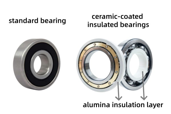
Electrically insulated bearings interrupt the current path through the bearing by adding a high-resistance barrier between the rolling contact and either the shaft or the housing. Two main types are used in VFD motors:
- Ceramic-coated bearings: A plasma-sprayed alumina (or similar) layer on the outer ring or inner ring provides megohm-level resistance and high breakdown voltage.
- Hybrid bearings: Steel rings with ceramic rolling elements, typically silicon nitride balls. The balls themselves are non-conductive, breaking the circuit through the rolling contact.
In both cases, the goal is the same: block shaft current from crossing the bearing.
Electrical Performance
Properly designed insulated bearings typically offer:
- Insulation resistance on the order of tens of megaohms or higher.
- Dielectric strength sufficient to withstand standard VFD-induced shaft voltages.
- Stable performance over time when protected from heavy contamination and mechanical abuse.
By raising the impedance of the bearing path, they force shaft currents to return via other, safer routes (for example, shaft grounding rings or cable shields), dramatically reducing EDM damage.
Why VFD Motors Specifically Require Insulated Bearings
VFDs Greatly Increase Bearing Current Risk
Compared with across-the-line operation, VFD-driven motors have:
- Higher standard-mode voltage at the terminals.
- More high-frequency content and steeper dv/dt.
- Greater capacitive coupling between stator and rotor.
This makes them far more likely to develop damaging bearing currents, even in smaller frame sizes. As a result, many motor and drive manufacturers now recommend or require insulated bearings in VFD applications, particularly for:
- Motors above a certain power rating (e.g., > 30-75 kW / 40-100 HP).
- High switching-frequency drives.
- Installations with long motor leads.
Protection of Both Motor and Driven Equipment
If the motor shaft is electrically continuous with the driven machine (pump, gearbox, fan), shaft currents can bypass the motor bearings and attack bearings in the driven equipment instead. Using insulated bearings on at least one end of the motor helps:
- Protect the motor bearings themselves.
- Limit current propagation into connected machinery.
For many large VFD motors, best practice is a combination: an insulated bearing on one end, shaft grounding on the other, so the current path is controlled and does not “hunt” through random bearings.
Types of Electrically Insulated Bearings for VFD Motors
Ceramic-Coated (INSOCOAT Type) Bearings
i. Construction: Standard steel bearing with the outer or inner ring coated with plasma-sprayed ceramic (commonly alumina).
ii. Advantages:
- Drop-in dimensional interchangeability with standard bearings.
- High insulation resistance and good dielectric strength.
- Robust mechanical load capacity identical to steel bearings.
- Often the most economical solution for medium- to large-frame motors.
iii. Use cases:
- Industrial VFD motors, pumps, compressors, fans.
- Generator ends of wind turbines and large alternators.
Hybrid Ceramic Bearings
i. Construction: Steel rings with ceramic balls.
ii. Advantages:
- Complete insulation through the rolling elements.
- Lower mass and reduced centrifugal forces at high speed.
- Lower friction and potentially better high-speed performance.
iii. Use cases:
- High-speed VFD motors and spindles.
- Aggressive duty cycles where both electrical and thermal performance are critical.
Both styles can be used successfully in VFD motors. The choice depends on shaft voltage level, speed, cost targets, and mechanical requirements.
Where to Place Insulated Bearings in a VFD Motor
A typical practical question is which end of the motor should have the insulated bearing.
- Smaller motors (up to a specific frame size): One insulated bearing-often on the non-drive end (NDE)-is frequently sufficient to block most circulating currents.
- Larger motors: One insulated bearing plus a shaft grounding ring on the opposite (drive) end is widely recommended to handle both circulating currents and capacitive discharge.
- Hazardous locations or very high shaft voltages: Some designs use insulated bearings at both ends, sometimes combined with external grounding.
Motor OEM guidelines and frame-size recommendations should always be followed, but the key principle is: at least one current path must be deliberately controlled, and bearings should not be that path.
Practical Selection Guidelines for Engineers
Assess Electrical Stress
Consider:
- Drive DC bus voltage and output voltage.
- Switching frequency and modulation strategy.
- Cable length, type, and routing between VFD and motor.
- Whether the system has any common-mode chokes or dv/dt filters.
Higher voltages, higher frequencies, and long cables all increase the risk of bearing currents and strongly argue for insulated bearings.
Consider Motor Size and Criticality
- For large motors (> 100 HP / 75 kW) or critical process equipment, insulated bearings are usually a must.
- For smaller motors in non-critical service, the cost-benefit calculation may depend on expected running hours, environment, and downtime impact.
Choose Coated vs Hybrid
- Coated bearings: preferred for general industrial motors where cost, availability, and mechanical robustness are priorities.
- Hybrid bearings: preferable where high speed, low friction, or exceptionally high shaft voltages are present.
Match Fits, Clearances, and Lubrication
Ensure:
- Proper fits on the shaft and housing that do not damage the coating.
- Correct internal clearance (often C3 or higher for larger motors or interference fits).
- Lubricant compatible with both steel and ceramic interfaces and appropriate for VFD-related temperature profiles.
Recommended Insulated Bearing Models for VFD Applications
Selecting the correct part number is crucial for VFD motor protection. Below is a list of common ISO standard sizes often stocked with ceramic insulation (typically on the outer ring) suitable for motors ranging from 30kW to 500kW+.
Deep Groove Ball Bearings (Non-Drive End / Drive End):
- 62 Series: 6210-J20AA, 6212-J20AA, 6216-J20AA … up to 6230-J20AA
- 63 Series (Heavy Duty): 6310-J20AA, 6314-J20AA, 6316-J20AA, 6322-J20AA, 6328-J20AA
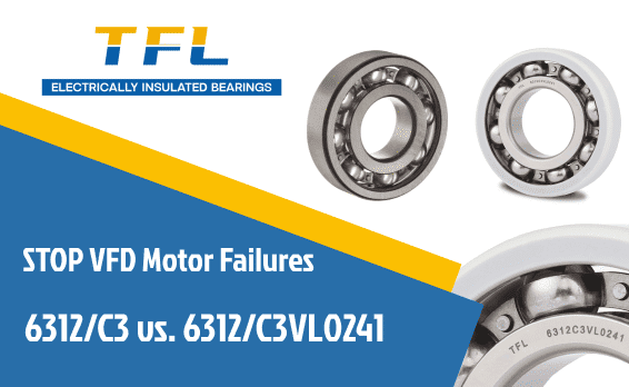
- Note: The suffix J20AA, J20AB, or VL0241 indicates an electrically insulated coating.
Cylindrical Roller Bearings (Drive End for High Radial Loads):
- NU 2 Series: NU 214-ECM-J20AA, NU 220-ECM-J20AA
- NU 3 Series: NU 316-ECM-J20AA, NU 322-ECM-J20AA, NU 330-ECM-J20AA
- Application: Ideally suited for the drive end (DE) of belt-driven VFD motors where radial loads are high.
TFL Insulated Bearings offers full interchangeability with these standard designations, ensuring a hassle-free upgrade for your VFD motors.
Installation and Handling Best Practices
To get the full benefit from insulated bearings:
- Do not strike or pry on coated surfaces. Use induction heaters, presses, and installation tools on uncoated faces.
- Keep the coating clean and dry-avoid metallic debris and conductive films.
- On hybrid bearings, handle ceramic balls with extra care to avoid impact loading during mounting.
- When combining insulated bearings with grounding rings, follow the recommended configuration (e.g., insulated NDE, grounding ring on DE) and ensure good ground bonding.

Monitoring and Verification in Service
Insulation Resistance Checks
Some users periodically measure insulation resistance between the shaft and frame to confirm that the insulated bearing and overall system still provide adequate isolation. Declining insulation resistance can indicate:
- Coating damage or wear.
- Contamination and moisture are bridging the insulation.
- Unintended conductive paths through couplings or connected equipment.
Vibration and Noise
Bearings protected from shaft currents should not show the characteristic electrical fluting patterns. If new tonal noise or high bearing frequency vibration appears in a VFD motor that has insulated bearings, it’s a sign to:
- Check grounding devices.
- Verify cable and filter configuration.
- Inspect the bearing for other mechanical issues (lubrication, misalignment, contamination).
Typical Benefits of Electrically Insulated Bearings in VFD Motors
Extended Bearing and Motor Life
Insulated bearings:
- Eliminate electrical pitting and fluting as a failure mode.
- Prevent secondary damage to rotor, stator, and housings from debris.
- Support the motor in achieving its intended mechanical L10 life instead of failing early from electrical erosion.
Reduced Downtime and Maintenance Costs
By preventing recurrent bearing failures, insulated bearings:
- Cut the number of emergency motor pulls and rebuilds.
- Reduce lost production time and service labor.
- Make it easier to move from reactive to planned maintenance.
Improved Reliability and Customer Satisfaction
For OEMs and integrators, specifying insulated bearings in VFD motors:
- Reduces field warranty claims tied to “mysterious” bearing failures.
- Helps motors meet noise and vibration expectations, particularly in HVAC and EV applications.
- Strengthens the overall reliability story of the drive-motor package.
Table: When to Use Electrically Insulated Bearings
| Situation / Parameter | Recommendation |
| Motor on VFD, > 75 kW (100 HP) | Always use insulated bearings, plus grounding if possible. |
| Long motor leads or high switching frequency | Strongly recommended, even on smaller motors. |
| Critical process motor (high downtime cost) | Use insulated bearings regardless of size. |
| The motor is directly coupled to sensitive equipment. | Insulated bearing on the motor, plus check bearings in the load. |
| Across-the-line motor, short cables | May not require insulation; evaluate on a case-by-case basis. |
VFD technology delivers significant energy and process benefits, but it also creates shaft currents that can destroy unprotected motor bearings long before their mechanical life is reached. Electrically insulated bearings-whether ceramic coated or hybrid-break the current path through the rolling elements, stopping electrical pitting and fluting at the source.
For practical engineering and maintenance teams, the message is clear: any significant VFD motor should be evaluated for insulated bearings. When combined with proper grounding, proper cabling, and basic installation care, insulated bearings turn VFD-induced shaft currents from an unpredictable failure mechanism into a manageable design issue, delivering more extended life, higher reliability, and lower total cost of ownership for modern electric drive systems.
Secure Your VFD Motors with TFL Insulated Bearings
At TFL Insulated Bearings, we know that modern VFDs are great for efficiency but tough on bearings. We have seen firsthand how quickly a standard steel bearing can fail under high-frequency electrical stress. That is why we specialize in manufacturing premium ceramic-coated bearings designed specifically to withstand the rigors of PWM switching and common-mode voltages.
Don’t let shaft currents compromise your critical assets.
- Need a replacement fast? We stock a wide range of VFD-compatible sizes.
- Unsure about the specs? Our engineers can help you choose between coated and hybrid options.
Take the Next Step Toward Reliability:
- Email Us: [email protected]
- Call Us: +86 15806631151
- Quick Quote: Click the “Contact us” popup on the sidebar to send your inquiry instantly.
Stop electrical fluting before it starts. Choose TFL Insulated Bearings.